
When we think about how computers work, we can break down any task into three basic parts:
- Getting information In
- Doing Something with it
- Getting something Out
This idea, known as the IPO model, has been around since the beginning of computers and is still the best way to understand how machines work. It’s made up of Input where the computer gets the information it needs. Processing where it does the work, and Output where it shows us the results. This simple way of thinking about it helps us make sense of everything from loading a website to teaching a computer to recognize pictures.
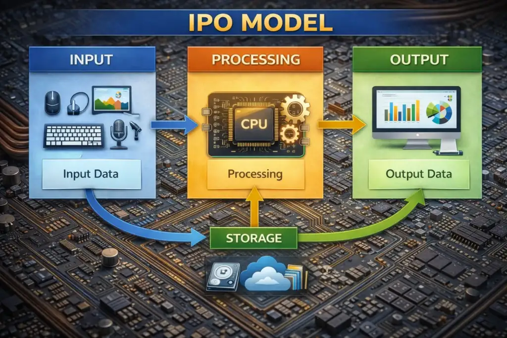
Core Definition
Input is any data or instruction fed into a computer system.
Processing is the transformation of that raw data by the CPU using arithmetic, logic, and control operations.
Output is the result communicated back to the user or stored for later use.
The model also has a fourth part that’s not always visible – Storage. This part holds data while it’s moving from the input stage to the processing stage, and it keeps the results after they’ve been output. This bigger IPOS model gives a more accurate picture of how real systems work, where data goes through many steps like registers, cache, RAM, and secondary storage before and after it’s processed. INPUT → [ STORAGE ↔ CPU ↔ MEMORY ] → OUTPUT To get the most out of your system, you need to really understand how it works. This means looking closely at each part of the process.
Classification of Input Devices
Input devices are hardware components or software mechanisms that allow humans (or other machines) to communicate data and instructions to a computer. They can be classified along several Dimensional Categories.
Examples : Data Type Text, Numeric, Image, Audio, Video, Biological Keyboard, Scanner, Microphone, Camera, Fingerprint sensor Interaction Mode Direct, Indirect Touchscreen (direct); Mouse (indirect) Human Sense Used Visual, Motion sensor Signal Type Analogue, Digital Analogue joystick; Digital keyboard Interface USB, Bluetooth, PS/2, Wireless RF, PCIe USB mouse, BT keyboard, RF remote.
This taxonomy matters because the type of input determines how data must be conditioned and encoded before it reaches the CPU. An analogue microphone signal must be sampled and quantised by an Analogue-to-Digital Converter (ADC) before it becomes processable binary data.
A USB keyboard, by contrast, already transmits discrete digital scan codes. Keyboard & Pointing Devices The Keyboard The keyboard is still the most widely used way to input text. Every key has its own special code, called a scan code. When you press a key, the keyboard’s tiny computer, or microcontroller, sends a message to the host computer, called a make code.
Then, when you let the key go, it sends another message, called a break code. This helps the computer’s operating system keep track of when multiple keys are pressed at the same time, which is called rollover. Today’s keyboards usually use one of three main types of switches: Membrane A pressure-sensitive membrane beneath keys completes a circuit on press. Quiet, cheap, low profile. Common in laptops and office keyboards. Mechanical Individual switches per key (Cherry MX, Topre, etc.). Tactile feedback, longer lifespan (~50M actuations), preferred for typing accuracy and gaming. Optical Infrared beam interruption replaces physical contact. Zero debounce delay, consistent actuation, immune to contact wear. Emerging high-performance standard.
Scanning, Imaging & Optical Input Flatbed Scanners & OCR
A flatbed scanner moves a CCD (Charge-Coupled Device) or CIS (Contact Image Sensor) array across a document, capturing reflected light at each pixel. The output is a raster image which can then be passed to Optical Character Recognition (OCR) software. OCR systems use pattern recognition — historically template matching, now deep convolutional neural networks — to convert image regions into machine-readable text. Modern OCR engines (e.g., Tesseract 5, Google Cloud Vision) achieve >99% character-level accuracy on clean printed text.
Barcode & QR Code Readers 1D barcodes encode data as variable-width parallel lines read by a laser beam or camera. QR codes (Quick Response) are 2D matrix barcodes storing up to 4,296 alphanumeric characters using a grid of black and white squares. Three finder patterns in corners allow the reader to determine orientation and perspective regardless of angle. QR codes include error-correction redundancy (Reed-Solomon coding) at four levels (L/M/Q/H), allowing up to 30% of the code to be damaged while still being decoded correctly. Digital Cameras & Video Input Digital cameras capture light via CMOS or CCD image sensors.
Application Domain In self-driving cars, cameras send lots of raw picture data to special computer programs called deep neural networks. These programs, which include CNNs and Transformers, can find lanes, obstacles, and traffic signs really fast – more than 30 times per second. All of this happens in real-time, thanks to powerful computer chips called GPUs and special chips called ASICs that are built into the car. This shows how closely the cameras and computer chips work together to make the car drive itself.
Audio, Voice & Biometric Input Microphones & Analogue-to-Digital Conversion
When sound waves reach a microphone, they cause pressure changes that get turned into an electrical voltage. This voltage is like a continuous wave, but to work with it digitally, we need to break it down into smaller parts. We do this by taking samples of the voltage at regular time intervals. The key to doing this correctly is to sample the signal often enough. If we don’t, we might lose important details.
Biometric systems
Biometric systems use physiological or behavioural characteristics as input. The processing pipeline involves sensor capture → feature extraction → template matching → decision.
Fingerprint Capacitive sensors map ridge/valley patterns. Minutiae points (ridge endings, bifurcations) are extracted and compared against stored templates. FAR/FRR trade-off governs security. Iris Recognition Near-infrared illumination captures iris texture. Daugman’s IrisCode encodes patterns into 2048-bit binary codes; Hamming distance measures similarity with very low false accept rates (~1 in 1.2 million).
Face Recognition CNN-based models (e.g., FaceNet, ArcFace) extract 128–512 dimensional embeddings; identity is determined by cosine similarity in embedding space. 3D depth maps (Face ID) resist spoofing. Specialised & Emerging Input Technologies Game Controllers & Motion Sensors Modern game controllers integrate multiple input modalities: digital buttons, analogue sticks (potentiometer-based or Hall-effect), triggers, haptic actuators, gyroscopes, and accelerometers.
Brain-Computer Interfaces (BCI)
BCIs represent the frontier of input technology. Non-invasive systems (EEG headsets) measure electrical potentials on the scalp corresponding to neural activity. Signals are band-pass filtered, artefact-removed (eye blinks, muscle noise), and classified using machine learning to decode mental states or intended commands. Invasive BCIs (e.g., Neuralink’s Utah Array) insert electrode arrays directly into cortical tissue, achieving far higher spatial resolution.
The Central Processing Unit
The brain of a computer is basically its CPU. This is where all the information from keyboards, mice, and other input devices goes to be understood and changed. A modern CPU is really complicated, with billions of tiny parts called transistors that work together to follow instructions from programs. These transistors are arranged into different groups that specialize in different tasks, kind of like how different parts of our brain do different things. When you put it all together, the CPU is what makes a computer able to do all the things it does.
Core Components
ALU Arithmetic Logic Unit. Performs integer arithmetic (+, −, ×, ÷), bitwise logic (AND, OR, XOR, NOT), and comparison operations. The computational workhorse of every instruction.
Control Unit Decodes instructions fetched from memory and orchestrates the activities of all other CPU components. Generates control signals that sequence operations precisely. Registers Ultra-fast, on-chip storage (sub-nanosecond access). Includes general-purpose registers (RAX–R15 in x86-64), the Program Counter (PC), Stack Pointer (SP), and Flags Register. FPU The Floating-Point Unit is a part of the computer’s brain that helps with really complicated math problems, especially those that need decimals, like science and graphics stuff. Nowadays, most computer chips have special helpers called SIMD units, like SSE and AVX-512, that can do lots of these math problems at the same time, making things faster.
Clock Speed & IPC So when we’re talking about how fast a computer’s brain, or CPU, works, it’s not just about how many times it can do something per second, which is measured in GHz. It’s also about how much it can actually get done each time it does something, which is called Instructions Per Clock, or IPC for short. Think of it like a factory – just because a factory can produce something really fast, doesn’t mean it’s producing a lot of things. If two factories are working at the same speed, but one can make more things each time it works, that one is going to be way more productive. This is kind of like what’s happening with AMD’s Zen 4 and Intel’s Raptor Cove – they’re making their factories, or CPUs, way more efficient without using a lot more power. This means they can get more done without getting too hot or using too much energy
Performance Formula CPU Performance = Clock Speed (GHz) × IPC × Number of Cores (for parallelisable workloads).
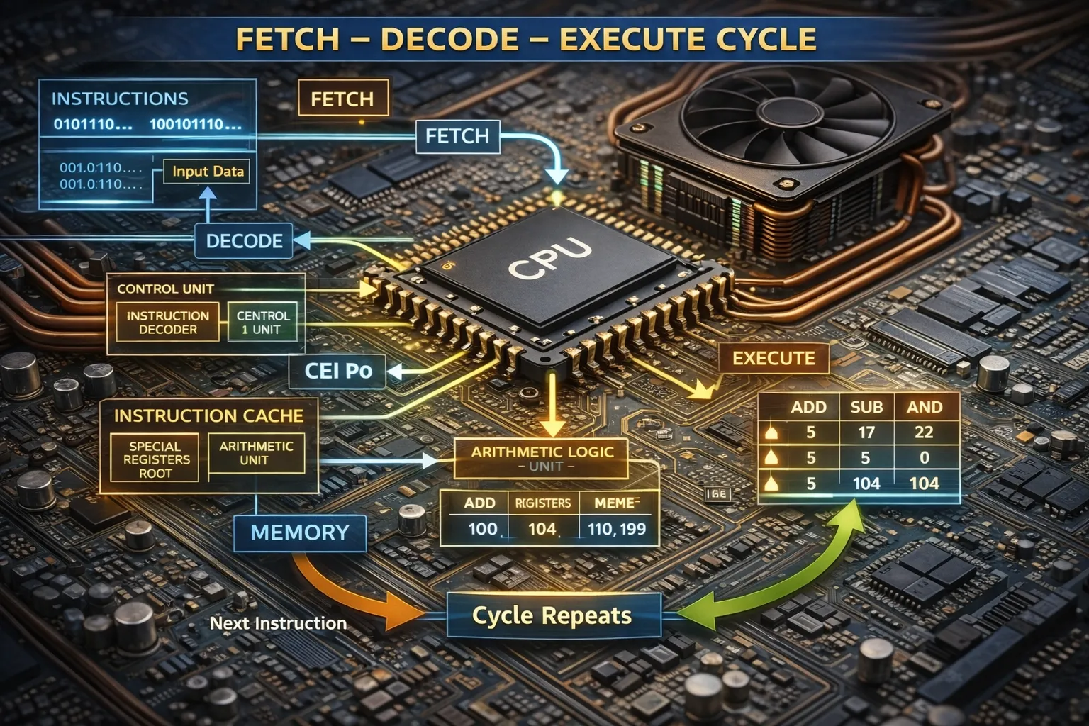
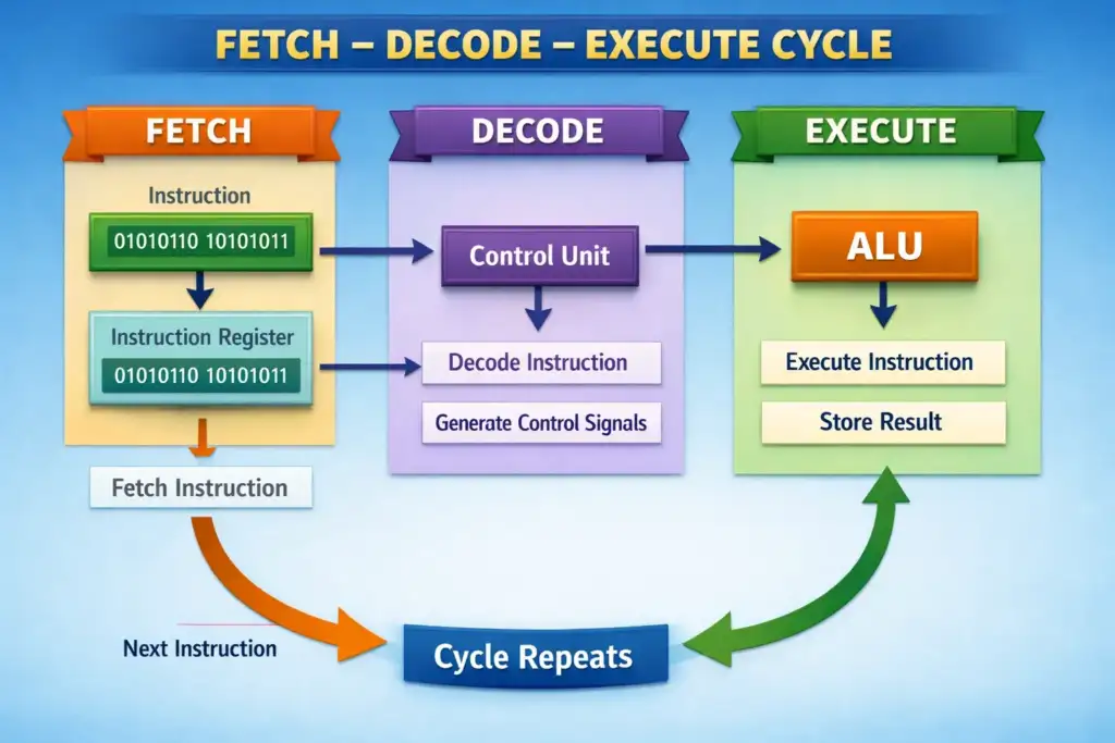
The Fetch–Decode–Execute Cycle
The Fetch–Decode–Execute (FDE) cycle is the fundamental operational loop of every von Neumann CPU. It describes the sequential steps by which the processor retrieves, interprets, and carries out each instruction in a program.
1. Fetch
The Control Unit looks at the address in the Program Counter, sends it to the Address Bus, and then gets the instruction from that address through the Data Bus. This instruction goes into two registers: the Memory Address Register and the Memory Data Register.
From there, it’s moved to the Current Instruction Register. Then, the Program Counter is updated to point to the next instruction, so everything is ready for the next step.
2. Decode
The Control Unit dissects the binary instruction in the CIR into its constituent fields: the opcode (operation to be performed) and operands (data or addresses to be used). The opcode is looked up in the instruction set, and the appropriate control signals are prepared. Addressing mode (immediate, direct, indirect, register) determines how the operand is interpreted.
3. Execute
When the computer decodes an operation. If it’s a math problem, the computer does the calculation and stores the answer in a special place called a register. If it’s a memory operation, the computer either gets data from the memory or puts data into it. And if it’s a branch instruction, the computer might change where it’s looking in the program, so it can do something different next. The computer also keeps track of some important things, like if the answer is zero, if it had to carry a number, if it got too big, or if it’s positive or negative. All these things help the computer know what to do next.
4.Write-Back (extended)
In a pipelined system, there’s a special stage called write-back that takes the result from the execute stage and puts it into the right register. This step finishes off the instruction. By doing it this way, the pipeline can start getting the next instruction while it’s still working on the last one. This helps things move faster because it doesn’t have to wait for everything to be done before starting something new. Pipelining Real CPUs overlap the FDE stages of multiple instructions simultaneously — a technique called pipelining. A 5-stage pipeline (IF, ID, EX, MEM, WB) can have five different instructions in different stages at any one time, effectively increasing throughput (not latency).
Processing to Output
Closing the Loop Processed data exits the CPU and travels via system buses to output subsystems. The system bus comprises three sub-buses: the Address Bus (unidirectional, specifies memory location), Data Bus (bidirectional, carries data), and Control Bus (bidirectional, carries timing and control signals). Bus width (32-bit, 64-bit) determines how much data can travel in one cycle; the PCIe bus used for GPU communication can deliver over 128 GB/s in PCIe 5.0 ×16 configuration. The Role of the Operating System
The OS sits between applications and hardware, managing input from device drivers, scheduling CPU time across processes, and arbitrating memory access. Device drivers translate generic OS input/output requests into device-specific commands. The kernel’s interrupt handling mechanism is fundamental: when a key is pressed or a network packet arrives, the device raises an interrupt, the CPU suspends its current execution, saves its state, and jumps to an Interrupt Service Routine (ISR) that processes the new input before returning to the original task.
Real-Time Processing Constraints
Some systems, like medical equipment and aircraft controls, need to work in real-time. This means they have to process information and give answers within a very short, fixed time. To make this happen, special operating systems called Real-Time Operating Systems (RTOS) are used. Examples of RTOS include FreeRTOS and VxWorks. These systems use a special way of scheduling tasks based on priority, which guarantees that they can respond quickly enough, even in the worst-case scenario. This is different from regular operating systems, which are designed to work well on average, but might not always meet the strict time limits needed for real-time systems.
System Integration The entire journey — keypress → USB scan code → OS kernel → application process → CPU computation → GPU render → display pixels — takes less than 15 milliseconds on a well-optimised system. Each microsecond saved anywhere in this pipeline contributes to the responsiveness that defines user experience quality.


2 Comments
Ayan aslam
June 3, 2026Plz matric tech subjects class 10
Health science tech
Biology tech
Physics tech
Chemistry tech
Sultan Tutor
June 6, 2026Download all your Tech Books from the Official Link https://pectaa.edu.pk/curriculum-compliance/